DRIVE LINE AND DIFFERENTIAL
Drive line:
- The purpose of the drive line is to transmit the drive from gear box to the rear axle with a smooth transmission of torque.
- Universal joints are fitted on both the ends of the shaft to maintain constant velocity and transmit the power at different angles.


Propeller shaft:
- Propeller shaft connects gearbox to the final drive gears of the vehicle through universal joint and serves as drive shaft.
- Shaft diameter and its thickness decide the torque carrying capacity and angle of operation.
- It is made of tubular cross section to withstand the torsional stress.
- It is made of alloy 303, steel and stainless steel.


Universal joint(Cardon
joint)
- It is a coupling or joint which can transmit rotary power between two inclined shafts at any selected angle.
- Simple type of universal joint is Hooke’s joint, It is efficient up to 18deg.
- It consists of two Y- shaped yoke(trunnions), one on the driving shaft and another on the driven shaft.
- Both are connected to the spider.


Single Hooke’s joint
- If a single Hooke's joint is used, velocity of driven shaft is not uniform even if driving shaft rotates at uniform velocity. This variation of speed is depicted on a polar diagram.


Double Hooke’s joint


Slip joint or sliding joint:
- Slip joint is attached to the driven yoke in order to increase or decrease the length of propeller shaft.
- It has outside splines on the shaft and matching internal splines in a mating hollow shaft or yoke.
- When assembled the splines cause the shafts to rotate together while they can move back and forth. This changes the length of propeller shaft.


Effect of Driving thrust and torque
reactions:

- Driving thrust is the force generated at the point of contact between vehicle tyre& ground due to the driving torque.
Te- Tractive effort
p-adhesion force
μ-
coefficient of friction
w- weight of the vehicle
t- driving torque
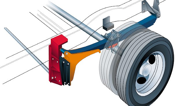
- The drive force from the wheels is transmitted to the body or chassis by means of leaf springs or Radius rods.
- If the road wheels are prevented from rotation, with propeller shaft rotating it is seen that the bevel pinion tend to roll around the crown gear of the differential It will tend to turn the casing which leads to lifting of front axle. This is called torque reaction.
- Torque applied at a wheel produces tractive effort at the road surface and equal opposite force at the propeller shaft.
Rear axle drive:
•Hotchkiss drive
•Torque tube drive
•De-dion drive
Hotchkiss
drive:
- Simplest and most widely used rear axle drive.
- Propeller shaft with two universal joints and a sliding joint.
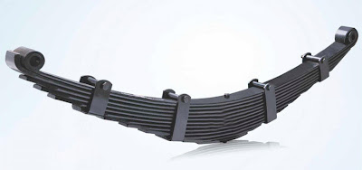
- The front end of the leaf suspension is rigidly fixed onto the frame while the rear is connected via a shackle.
- Body weight, Torque reaction, driving thrust and side thrust are taken up by the leaf spring.


Torque tube drive:

- The torque tube encloses the propeller shaft .
- One end of the torque tube is attached to the axle casing while the other end is fits into the spherical cup on the frame.
- The purpose of a torque tube is to hold the rear end in place during acceleration and braking. Otherwise, the axle housing would suffer axle wrap, such that the front of the differential would lift up excessively during acceleration and sink down during braking.
- The combination of the radius rod and the torque tube allows the easy implementation of soft coil springs in the rear to give good ride quality. Later leaf springs replaced the panhard rod.
- Torque reaction, Braking torque and drive thrust are taken by Torque tube(then to the frame) and side thrust and body weight are taken by the suspension springs.
- Centre line of the bevel pinion shaft always passes through the centre of the spherical cup.
- One constant velocity joint is used in the transmission drive because the joint is situated exactly at the centre of the spherical cup.
- No sliding joint is provided since the pinion shaft and the propeller shaft moves same centre.
- The torque tube design is typically heavier and securely ties the rear end together, thus providing for a rigid rear and assuring good alignment under all conditions. However, because of the greater unsprung weight of the torque tube and radius rods there may be a "little hopping around of the rear end when cornering fast.
De-Dion drive


Advantages:
1. Reduced unsprung weight.
2. No camber change.
3. Better ride quality than live axle
4. Cheaper than most independent suspensions
Dis-advantages:
It needs two CV joints per axle instead of only one.
Panhard Rod or track rod


- A panhard bar prevents the rear axle from moving side-to-side during side-thrust(During cornering cross-winds, cornering force or irregular load causes side thrust). The bar attaches on either end with pivots that let it swivel upwards and downwards only, so that the axle can move in the vertical plane only.
- This arrangement is not usually used with a leaf spring suspension, where the springs themselves supply enough lateral rigidity, but only with coil spring suspensions.
Used in: Mercedes G-class
Radius Rod or torque arm

- A radius rod is a suspension link intended to control wheel motion in the longitudinal direction.
- It is mounted ahead of the wheel to resist dive under braking forces and wheel lift under acceleration.
- Radius rods are customarily made of stamped steel or aluminum for lightness, as they are part of the vehicle's unsprung weight.
Used in: ATVs, Ford Excursion

- Constant-velocity joints allow a drive shaft to transmit power through a variable angle.
- C.V joints are used mainly in the front axle to facilitate steering and power transmission at the same time.
Types:
1.By position
Two CV joints are used on each half shaft
i)inboard(plunging)
ii)outboard(fixed)
2. By function
i)Fixed joints
They do not plunge in and out to compensate for changes in length
ii)Plunge Joints
Plunge in and out to compensate for changes in length due to the suspension action
Ball-Type Joints:
Fixed and plunging

Tripod-type joints:
Fixed and plunging

Tripod joint


 |
| Tripod-type joint: |
Rzeppa Joint


Differential(Final drive)

Functions:
- To allow the wheels to rotate at different speeds
- To turn the angle of power transmission perpendicularly.
- To provide permanent gear reduction(4:1 in cars and 10:1 in heavy vehicles).

- Car wheels spin at different speeds, especially when turning that each wheel travels a different distance through the turn, and that the inside wheels travel a shorter distance than the outside wheels. Since speed is equal to the distance traveled divided by the time it takes to go that distance, the wheels that travel a shorter distance travel at a lower speed.
- The differential is a device that splits the engine torque two ways, allowing each output to spin at a different speed.


- Without the differential, the wheels would have to be locked together, forced to spin at the same speed. This would make turning difficult and hard on the vehicle.
- For the car to be able to turn, one tire would have to slip. With modern tires and concrete roads, a great deal of force is required to make a tire slip. That force would have to be transmitted through the axle from one wheel to another, putting a heavy strain on the axle components.
Working

1.Straight bevel gear
- Straight teeth, simple and cheap.
- At an instant only one teeth pair is engaged , results in uneven transmission motion when load is transferred from one pair to another. This causes high wear and noise.

2.Spiral bevel gear
- Curved teeth
- Greater contact area
- Silent operation
- Stronger than straight bevel gears

3.Hypoid gears:
- Widely used for final drive. It is used to connect shaft at right angles.
- Pinion axis is located below the crown axis(lower position of the propeller shaft).
- The pinion has more pitch diameter(increase the pinion strength by about 20-30%).
- Silent running
- Crown wheel, pinion and shaft are made of Nickel-Chrome alloy steel.
Disadvantages:
Less ground clearance, expensive, and difficult to assemble.


4.Worm and wheel

- Axle ratio is 6:1 for heavy vehicles.
- Large gear reduction is possible in single stage compared to pinion.
- Worm axis is located below or above the wheel axis.
Dis-advantages:
- Lubrication is difficult.
- Mechanical efficiency is lower than bevel gears in single stage reduction.
- More cost and weight than bevel gears
Rear axle ratio = no of teeth on pinion/no of teeth in crown
- Open differential
- Limited slip or clutch type or non-slip differential
- Locked differential
- Double reduction differential
1. Open differential


- The simplest type of differential, called an open differential.
- When a vehicle is moving straight down the road, both drive wheels are spinning at the same speed. The input pinion is turning the ring gear and cage, and none of the pinions within the cage are rotating -- both side gears are effectively locked to the cage.
- When a car makes a turn, the wheels must spin at different speeds.
- When the car makes a turn, planet gears in the cage start to spin as the car begins to turn, allowing the wheels to move at different speeds. The inside wheel spins slower than the cage, while the outside wheel spins faster.
2. Limited slip differential
- It can be used in rear wheel drive vehicles only.
- It may be clutch type or hydraulic or gear type or viscous type or electronic.


- Clutch type
- Geared type
- Viscous type
- Gerotor pump
- Electronic traction control
1. Torque-sensitive(Clutch type or geared)
2. Speed-sensitive(Viscous or pump and clutch or electronic type)
3.Locked differential

- Used for off-road vehicles.
- Both the axles are locked together.
- All the wheels will rotate at the same speed.
Dis-advantage
In corners both wheels rotates at same speed, so we can use ABS in open differential.


Gear reduction occurs in 2 stages .Mostly used in heavy vehicles where high amount of torque is required such as military vehicles.


gear reduction in most automobiles and light- and some medium- duty trucks between the drive shaft and the wheels.Double-reduction final drives are used for heavy-duty trucks. With this arrangement (fig.) it is not necessary to have a large ring gear to get the necessary gear reduction. The first gear reduction is obtained through a pinion and ring gear as the single fixed gear reduction final drive. Referring to figure 5-14, notice that the secondary pinion is mounted on the primary ring gear shaft. The second gear reduction is the result of the secondary pinion which is rigidly attached to the primary ring gear, driving a large helical gear which is attached to the differential case. Double-reduction final drives may be found on military design vehicles,such as the 5-ton truck. Many commercially designed vehicles of this size use a single- or double-reduction final drive with provisions for two speeds to be incorporated.

Comments
Post a Comment