STEERING AND FRONT AXLE
The Ackermann Principle
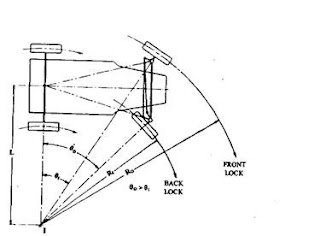
If the instantaneous centre of the two front wheels do not coincide with the instantaneous centre of the back wheels, the skidding on the front or back wheels will definitely take place, which will cause more wear and tear of the tyres. Thus, the condition for correct steering is that all the four wheels must turn about the same instantaneous centre. The axis of the inner wheel makes a larger turning angle than the angle subtended by the axis of outer wheel.
To achieve true rolling for a four wheeled vehicle moving on a curved track, the lines drawn through each of the four wheel axes must intersect at the instantaneous centre (Fig). The actual position the instantaneous centre constantly changes due to the alternation of the front wheel angular positions to correct the steered vehicle’s path. Since both rear wheels are fixed on the same axis but the front wheel axles are independent of each other , the instantaneous centres lies somewhere along an imaginary extended line drawn through the axis of the rear axle.
The Ackermann principle is based on the two front steered wheels being pivoted at the ends of an axle-beam. The original Ackermann linkage has parallel set track-rod-arms, so that both steered wheels swivel at equal angles. Consequently, the intersecting projection lines do not meet at one point (Fig). If both front wheels are free to follow their own natural paths, they would converge and eventually cross each other. Since the vehicle moves along a single mean path, both wheel tracks conflict continuously with each other causing tyre slip and tread scrub. Subsequent modified linkage uses inclined track-rod arms so that the inner wheel swivels about its king-pin slightly more than the outer wheel. Hence the lines drawn through the stub-axles converge at a single point somewhere along the rear-axle projection.
 |
| Side-pivot steering with parallel-set track-rod arms |
 |
| Side-pivot steering with inclined track-rod arms in Ackermann steering |
 |
| Ackerman steering |
Davis steering mechanism

The Davis Steering gear has sliding pair, it has more friction than the turning pair, there fore the Davis Steering Gear wear out earlier and become inaccurate after certain time. This type is mathematically accurate.
The slotted line AG & CH are attached to left & right wheel respectively & are arranged to turn on pivot at A & C respectively. The angle AGC & CHA are made equal. The line GH which is in front of the link AC, is at a distance 'h' from the line AC. The link GH is constrained to move in the direction of its length & parallel to AC the sliding constraints at E & F. The line EF is connected to the slotted levers AG & CH by a sliding & turning pair at each end. When the mechanism is in the mid position, with the wheels at orientation X1&X2, the vehicle moves along a straight path. Steering is effected by moving the GH to the right or left of its normal position. Fig shows the position of the various links when steering is effected to the left. Now, the wheels occupy the orientation X1X1' & X2X2'. Now , the axes of the left & right wheels (X1X1' & X2X2') make an angle θ & Ф respectively as shown with the axis of the rear wheels extended to the left.


Comments
Post a Comment